LEDmePlay®
LEDmePlay® Draw is a paint program for the LEDmePlay® written in Processing. Processing is an easy to learn language for designers and artists. It is based on the popular Java programming language. You can download it from https://processing.org/download/. A ready-made package of LEDmePlay® Draw can be executed by clicking its icon on the Windows, Mac OS X or Linux desktop. Alternatively, the source code of the program can be loaded and executed from within the Processing environment. Please read the section on installing LEDmePlay® Draw for details.
Scope
LEDmePlay® Draw was written in order to be able to draw LEDmePlay® images on an Windows PC and embed them into an Arduino sketch for the LEDmePlay®.
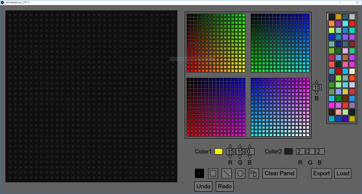
As Processing does not provide for user interface elements such as pull down menus, sliders, buttons and so on, one needs to invent one's own interface elements, as you can see in the screenshot above.
The LED matrix panel that is built into the LEDmePlay® offers 16 levels for each of the three color channels R, G, and B (R = red, G = green, B = blue) for a total of 4096 different colors. With LEDmePlay® Draw, you can draw images for your own LEDmePlay® games, save them to your PC's harddisk, or embed an image right into your Arduino sketch. LEDmePlay® Draw produces the necessary Arduino program code for you. The program is mouse-controlled.
Installation
You should have downloaded the ZIP file LEDmePlayDraw.zip from this website. Copy it to a location you want it to be, then unzip it. Within the newly deflated directory are the two folders LEDmePlayDraw.windows32, LEDmePlayDraw.windows64, the font file ArialMT-30.vlw, two example files carRace_Arduino and carRace_reimport and LEDmePlay® Draw's source code for Processing, LEDmePLayDraw_270117.pde. The suffix .pde might be invisible, dependent on your operating system's current parameter settings.
There are three ways how to execute LEDmePlay® Draw. All might work for you. Either download and install the Processing Environment and start the source code from there, or run the executable file for Windows. The third way is to export the source code from within the Processing IDE. More about this will follow later on. In any case the font file ArialMT-30.vlw needs to be present in the directory with the LEDmePlay® Draw source code or the LEDmePlay® executable, otherwise the application will not work. Please try one of the following alternatives:
1. Run the LEDmePlay® Draw source code
Download the Processing IDE for your operating system. Get it from https://processing.org/ and install it on your harddisk as described on their website.
Locate the file LEDmePlayDraw_270117.pde in the newly created directory obtained by deflating the ZIP file you downloaded. Please note that the date could be different, and the suffix may be invisible. Check that the font file ArialMT-30.vlw is present in the same directory. Also note that the directory bears the same name as the source code file. This is mandatory for the Processing Environment. If you double click the source code file, Processing 3 will be loaded and run and then show you the LEDmePlay® Draw source code in its window. From there you may click on the Play button on top left which will compile and run the LEDmePlay® Draw application. Alternatively, you can start the Processing IDE yourself and load the source code from there.
2. If your operating system is Windows 7/8/10, run the LEDmePlay® Draw executable in one of the subfolders LEDmePlayDraw_windows32 or LEDmePlayDraw.windows64 in the newly created directory that you obtained by deflating the ZIP file you downloaded from this website. The files ArialMT-30.vlw should also be in this folder. Double click on the executable file LEDmePlayDraw_270117.pde. This should start the application. Please note that the date could be different, and the suffix may be invisible. If the file in the directory with suffix windows32 does not work for you, try the windows64 version. If neither works for you, please see alternative 3 which follows. If your operating system is Mac OS X or a Linux OS, please see alternative 3.
3. Export the Processing project from within the Processing IDE.
Download the Processing IDE for your operating system. Get it from https://processing.org/ and install it on your harddisk as described on their website.
Start the Processing IDE via double clicking on its icon. Locate the LEDmePlay® Draw source code as described above and load it from within Processing. You should now see the source code. Select 'Export' from the File menu. Select your platform - either Windows, Mac OS X or Linux. If you like the application to run in fullscreen mode, select 'Presentation Mode'. However, I do not recommend this as you may want to use other applications besides LEDmePlay® Draw.
You may want to embed Java 8 right into the exported application. If you want to do this, you need to install Java 8 beforehand from https://www.java.com/download. See the documentation there. I suggest to make a first try without embedding Java 8 into the application. If it does not work then, you can repeat the procedure and embed Java 8.
Anyway, if you have made the necessary choices and then clicked the 'Export' button, Processing will export the LEDmePlay® source code (called a 'sketch' in Processing lingo) into an executable for your platform. Processing creates a new directory in the folder with the LEDmePlay® Draw sketch, LEDmePlayDraw.windows32 and LEDmePlayDraw.windows64 if you are on Windows. You can start the executable as usual by double-clicking on its icon. For further explanations, see alternative 2. For Linux and Mac OS X, the executables may look similar. However, I did not try it.
Elements in the Application Window
At the left side within its window, LEDmePlay® Draw shows an illustration of the LEDmePlay®'s LED matrix panel with stylized 1024 LEDs. This is the area in which all drawing operations take place. When you move the mouse over it, the drawing position under the mouse is highlighted. With the drawing tools, you may draw points, rectangles, or circles. You may also fill an enclosed area with a previously selected color, and you may clear the panel and start anew.
Situated at the right side are four color selectors. The upper left color selector features the colors with varying levels of red and green but no blue, the upper right has colors with varying levels of green and blue, the lower left with varying levels of red and blue. The lower right color selector is special, as it allows you to tweak the blue level between 0 and 15 using arrows. On the right edge of the window is another color selector with a palette that consists of 64 colors. You may alter any color within the color selectors. Doing so you can customize the colors for your project. The customized color palettes are saved along your image and are restored when you load a previously created image that has a name with the suffix _reimport.
On the lower part of the window, various controls are displayed. There are two color fields with names 'Color1' and 'Color2', each of which with RGB channel controls. For drawing on the LED matrix panel, you can always select between these. Once you click into one of the color selectors, the color under the mouse becomes either Color1 or Color2: Clicking the left mouse button selects Color1, clicking the right mouse button selects Color2.
There is a horizontal strip of icons with the drawing operations 'Point', 'Rectangle', 'Circle', 'Fill' and 'Clear Panel'. Two buttons allow for loading a previously drawn image or saving/exporting an image. Finally there are buttons named 'Undo' and 'Redo' that let you withdraw the last 100 editing steps or move between successive steps.
Using LEDmePlay® Draw
You start a drawing session either by loading an image or by starting with a blank image. The latter is the default state once the program has been started. With the exception of the color palette at the right side, which becomes filled with random colors, the palettes within the four color selectors are reset to their predefined state. If you load an image, it is displayed on screen along with the color palettes that are restored to the state they were during your drawing session. This means all changes you did to the colors in the palettes are being restored.
At the beginning the 'Point' drawing tool is selected. You may want to try to place some points on the LED matrix panel. Move over the panel and left-click into it. The program places a dot in Color1. If you right-click onto the LED matrix panel, the program draws a dot in Color2. Now select the icon with the rectangle in order to change the drawing mode to 'Rectangle'. Place the mouse over the LED matrix panel and drag the mouse (dragging = pressing a mouse button and holding it while moving). The program now continuously draws a rectangle that is defined by the position at which you started dragging and the current mouse position. Once you release the mouse button, the rectangle is drawn permanently on the LED matrix panel.
If you dislike your newly created rectangle, you may click on the 'Undo' button. This takes back your latest changes. If you then decide that your rectangle was not that bad, click 'Redo'. Your rectangle is restored. However, this functionality has a limitation worth knowing: Once you have modified an intermediate state of the Undo history, this deletes all future steps from the next point. This makes sense as all steps need to share a common history.
When you are satisfied with your image, left-click on the 'Save' icon. A file requester openes that lets you navigate the directories on your harddisk(s). Then type in a name for the image file, i. e., 'myName'. LEDmePlay® Draw will save two files, one with the suffix _Arduino, the other with the suffix _reimport. The _Arduino file contains code fragments that define your image and only the colors needed for it, whereas the "reimport" file contains a current snapshot of all colors within the palettes. This is the file you need to load if you want to modify your image from within LEDmePlay® Draw. Besides writing files, the application additionally copies the Arduino code fragments as text into the clipboard, a temporary buffer in your computer's memory. You may want to copy it from there into a text editor window or the Arduino IDE using Control + V. Saving and loading files may take a while, dependent on the speed of your hardware. Besides, as the structure I am currently using for saving the color palettes is very inefficient, it is the one culprit responsible for the slow speed.
Icons
Color Selectors, Color1 and Color2
LEDmePlay® Draw uses an indexed color palette. This means the entries in the color selectors are enumerated. Any color field within the color selectors is clickable. A click with the left mouse button makes the color 'Color1', a click with the right mouse button makes the color 'Color2'. The correspondent color field and the RGB channel entries right besides the 'Color1' and 'Color2' fields change accordingly. If you change the RGB channel values using the arrow selectors, the change is also reflected in the color selectors and - if you used the color in your image - also in the image. Additionally, the color the mouse is currently over is textually described in a text box below the LED matrix panel.
All changes in the color palettes are saved along with the actual image data in a file with suffix _reimport but not in the file with suffix _Arduino.
The first color in the palette to the right of the window, indicated by a vertical grey strip, is the background color - LED is off - and therefore immutable.
Saving image and palettes
Clicking on the icon 'Save' opens a file requester that lets you navigate to the location where you want to save your image. After specifying a name for your file(s), say 'myImage', two files are created, 'myImage_Arduino' and 'myImage_reimport'. The former file contains Arduino sketch code that you may embed into one of your sketches in order to display your image using approximately the colors you were using when you created the image on your computer. This text is also copied into the clipboard. You can paste it into the Arduino IDE or into a text editor window by holding down the keys CTRL (German keyboard: STRG) and V.
Please read the section below for more details. The latter, and only this, can be loaded back into LEDmePlay® Draw for editing.
Loading image and palettes
If you click on the icon 'Load', a file requester is displayed. Navigate your storage devices and select a file with suffix "_reimport". Doing so loads the image and restores the state of the color palettes to that of the drawing session. Do not try to open a file with suffix _Arduino, as these cannot be read from within LEDmePlay® Draw.
Drawing tools
The Point tool allows you to draw points in the LED matrix view by left or right mouse click. Left click uses 'Color1', right click uses 'Color2'.
The Rectangle tool lets you draw rectangles which are defined using two points. Define the rectangle by dragging and then releasing the mouse button.
With the Circle tool, you can draw circles which are defined using two points. Define the circle by dragging and then releasing the mouse button.
The Line tool allows you to draw lines. Click at a location within the LED matrix view and drag the mouse while holding down the mouse button. Releasing the mouse button fixates the line.
If you need to fill a region with a color, use the Fill tool. Click into an area that is enclosed fully by dots colors other than the color you clicked onto. This will fill the area with the currently selected 'Color1' or 'Color2'. If the border around the area has a gap, the fill color will "break out" of the area and might probably fill a large portion of the LED matrix.
A click onto the icon 'Clear Panel' clears the LED matrix.
The icons 'Redo' and 'Undo' allow you to move back and forth between the steps of the current image's editing history. If the current step is the latest, clicking on 'Redo' has no effect. Likewise, if you click on 'Undo' has no effect if the current step is the first. Changing something in an intermediate step invalidates all subsequent steps within the editing history. This is because these future editing steps do no longer reflect the history of the image.
For the editing history the outcome of all drawing operations and 'Clear Panel' are captured. 'Save' and 'Load' are excluded, however. Any modifications to color channels are also disregarded.
Embedding an Image in an Arduino Sketch
LEDmePlay® Draw would be of no use if it did not allow exporting an image into an Arduino sketch. In the following you will learn how to embed an image like this in an Arduino sketch.
Next comes the Arduino code that you find if you either open the file with suffix _Arduino within a text editor, or if you paste it into a text editor using CTRL/STRG+V.
// Code that displays an image based on an indexed color palette
void showImage()
{
int col;
byte p;
byte img[32 * 32];
matrix.fillScreen(0, 0, 0);
for (int k = 0; k < 32 * 32; k++)
{
img[k] = pgm_read_byte_near(img + k);
}
for (byte x = 0; x < 32; x++)
{
for (byte y = 0; y < 32; y++)
{
p = img[y * 32 + x];
switch(p)
{
case 0:
col = matrix.Color444(0, 0, 0);
break;
case 1:
col = matrix.Color444(0, 10, 3);
break;
case 2:
col = matrix.Color444(12, 0, 3);
break;
case 3:
col = matrix.Color444(12, 6, 0);
break;
case 4:
col = matrix.Color444(13, 14, 11);
break;
case 5:
col = matrix.Color444(13, 12, 7);
break;
case 6:
col = matrix.Color444(15, 0, 14);
break;
case 7:
col = matrix.Color444(15, 0, 0);
break;
case 8:
col = matrix.Color444(15, 0, 0);
break;
case 9:
col = matrix.Color444(4, 9, 11);
break;
case 10:
col = matrix.Color444(0, 9, 5);
break;
case 11:
col = matrix.Color444(11, 6, 0);
break;
case 12:
col = matrix.Color444(13, 7, 0);
break;
case 13:
col = matrix.Color444(10, 9, 14);
break;
case 14:
col = matrix.Color444(11, 13, 11);
break;
case 15:
col = matrix.Color444(13, 13, 11);
break;
case 16:
col = matrix.Color444(15, 15, 7);
break;
}
matrix.drawPixel(x, y, col);
}
}
// Image data
const uint8_t titleImg[] PROGMEM =
{
0, 0, 0, 0, 0, 0, 0, 0, 0, 0, 0, 0, 0, 0, 0, 0, 0, 0, 0, 0, 0, 0, 0, 0, 0, 0, 0, 0, 0, 0, 0, 0,
0, 0, 0, 0, 0, 0, 0, 0, 0, 0, 0, 0, 0, 0, 0, 0, 0, 0, 0, 0, 0, 0, 0, 0, 0, 0, 0, 0, 0, 0, 0, 0,
0, 0, 0, 0, 0, 0, 0, 0, 0, 0, 0, 0, 0, 0, 0, 0, 0, 0, 0, 0, 0, 0, 0, 0, 0, 0, 0, 0, 0, 0, 0, 0,
0, 0, 0, 0, 0, 0, 0, 0, 0, 0, 0, 0, 14, 14, 0, 0, 0, 0, 0, 0, 0, 0, 0, 0, 0, 0, 0, 0, 0, 0, 0, 0,
0, 0, 0, 0, 0, 0, 0, 0, 0, 0, 0, 0, 14, 9, 0, 0, 0, 0, 0, 0, 0, 0, 0, 0, 0, 0, 0, 0, 0, 0, 0, 0,
10, 10, 10, 10, 10, 10, 10, 10, 10, 10, 10, 10, 10, 10, 10, 10, 10, 10, 10, 10, 10, 10, 13, 10, 13, 10, 10, 10, 10, 10, 10, 10,
0, 0, 0, 0, 0, 0, 0, 0, 0, 0, 15, 0, 0, 0, 0, 0, 0, 0, 0, 0, 0, 0, 13, 0, 13, 0, 0, 0, 0, 0, 0, 0,
0, 0, 0, 0, 0, 0, 0, 0, 0, 0, 15, 0, 0, 0, 0, 0, 0, 0, 0, 0, 0, 0, 13, 13, 13, 0, 0, 0, 0, 0, 0, 0,
0, 0, 0, 0, 0, 0, 0, 0, 0, 15, 0, 0, 0, 0, 0, 5, 0, 0, 0, 0, 0, 0, 13, 0, 13, 0, 0, 0, 0, 0, 0, 0,
0, 0, 0, 0, 0, 0, 0, 0, 0, 15, 0, 0, 0, 0, 0, 7, 0, 0, 0, 0, 0, 0, 13, 13, 13, 0, 0, 0, 0, 0, 0, 0,
0, 0, 0, 0, 0, 0, 0, 0, 15, 0, 0, 0, 0, 0, 7, 0, 7, 0, 0, 0, 0, 0, 13, 0, 13, 0, 0, 0, 0, 0, 0, 0,
0, 0, 0, 0, 0, 0, 0, 0, 0, 0, 0, 0, 0, 4, 1, 4, 1, 4, 0, 0, 0, 0, 13, 13, 13, 0, 0, 0, 0, 0, 0, 0,
0, 0, 0, 0, 0, 0, 0, 0, 0, 0, 0, 0, 0, 0, 0, 0, 0, 0, 0, 0, 0, 0, 13, 0, 13, 0, 0, 0, 0, 0, 0, 0,
10, 10, 10, 10, 13, 10, 13, 10, 10, 10, 10, 10, 10, 10, 10, 10, 10, 10, 10, 10, 10, 10, 10, 10, 10, 10, 10, 10, 10, 10, 10, 10,
0, 0, 0, 0, 13, 0, 13, 0, 0, 0, 0, 0, 0, 0, 0, 0, 0, 0, 0, 0, 0, 0, 0, 0, 0, 0, 0, 0, 0, 0, 10, 10,
0, 0, 0, 0, 13, 13, 13, 0, 0, 0, 0, 0, 0, 0, 0, 0, 0, 0, 0, 0, 0, 0, 0, 0, 0, 0, 0, 0, 0, 0, 10, 10,
0, 0, 0, 0, 13, 0, 13, 0, 0, 0, 0, 0, 0, 0, 0, 0, 0, 0, 0, 0, 0, 0, 0, 0, 0, 0, 0, 0, 0, 0, 10, 10,
0, 0, 0, 0, 13, 13, 13, 0, 0, 0, 0, 0, 0, 0, 0, 0, 0, 0, 0, 0, 0, 0, 0, 0, 0, 0, 0, 0, 0, 0, 10, 10,
0, 0, 0, 0, 13, 0, 13, 0, 0, 0, 0, 0, 0, 0, 0, 0, 0, 0, 0, 0, 0, 0, 0, 0, 0, 0, 0, 0, 0, 0, 10, 10,
0, 0, 0, 0, 13, 13, 13, 0, 0, 0, 0, 0, 0, 0, 0, 0, 0, 0, 0, 0, 0, 0, 0, 0, 0, 0, 0, 0, 0, 0, 10, 10,
0, 0, 0, 0, 13, 0, 13, 0, 0, 0, 0, 0, 0, 0, 0, 0, 0, 0, 0, 0, 0, 0, 0, 0, 0, 0, 0, 0, 0, 0, 0, 0,
0, 0, 0, 10, 10, 10, 10, 10, 10, 10, 10, 10, 10, 10, 10, 10, 0, 0, 0, 0, 10, 10, 10, 10, 0, 0, 0, 0, 0, 0, 0, 0,
0, 0, 0, 0, 0, 0, 0, 0, 0, 0, 0, 6, 0, 0, 0, 8, 0, 0, 0, 0, 0, 0, 0, 0, 0, 0, 0, 0, 0, 0, 0, 0,
0, 0, 0, 0, 0, 0, 0, 0, 0, 0, 0, 6, 0, 0, 0, 8, 0, 0, 0, 0, 0, 0, 0, 0, 0, 0, 0, 10, 10, 10, 0, 0,
0, 0, 0, 0, 0, 0, 0, 0, 0, 0, 0, 6, 0, 0, 0, 8, 0, 0, 0, 0, 0, 0, 0, 0, 0, 0, 0, 0, 0, 0, 0, 0,
0, 0, 0, 0, 0, 0, 0, 0, 0, 0, 0, 6, 0, 0, 0, 8, 0, 0, 0, 0, 0, 0, 0, 0, 0, 0, 0, 0, 0, 0, 0, 0,
0, 0, 0, 0, 0, 0, 0, 0, 0, 0, 0, 6, 0, 0, 0, 8, 0, 0, 0, 0, 0, 0, 0, 0, 0, 0, 0, 0, 0, 0, 0, 0,
0, 0, 0, 0, 0, 0, 0, 0, 0, 0, 0, 6, 0, 0, 0, 8, 0, 0, 0, 0, 0, 0, 0, 0, 0, 0, 0, 0, 0, 0, 0, 0,
10, 10, 10, 10, 10, 10, 10, 10, 10, 10, 10, 10, 10, 10, 10, 10, 10, 10, 0, 16, 0, 16, 16, 0, 16, 3, 16, 0, 10, 10, 10, 10,
10, 10, 10, 10, 10, 10, 10, 10, 10, 10, 10, 10, 10, 10, 10, 10, 10, 10, 12, 11, 0, 11, 11, 0, 11, 11, 12, 16, 10, 10, 10, 10,
10, 10, 10, 10, 10, 10, 10, 10, 10, 10, 10, 10, 10, 10, 10, 10, 10, 10, 2, 2, 2, 2, 2, 12, 2, 2, 12, 2, 2, 10, 10, 10,
10, 10, 10, 10, 10, 10, 10, 10, 10, 10, 10, 10, 10, 10, 10, 10, 10, 10, 10, 2, 2, 2, 2, 2, 2, 2, 2, 2, 10, 10, 10, 10,
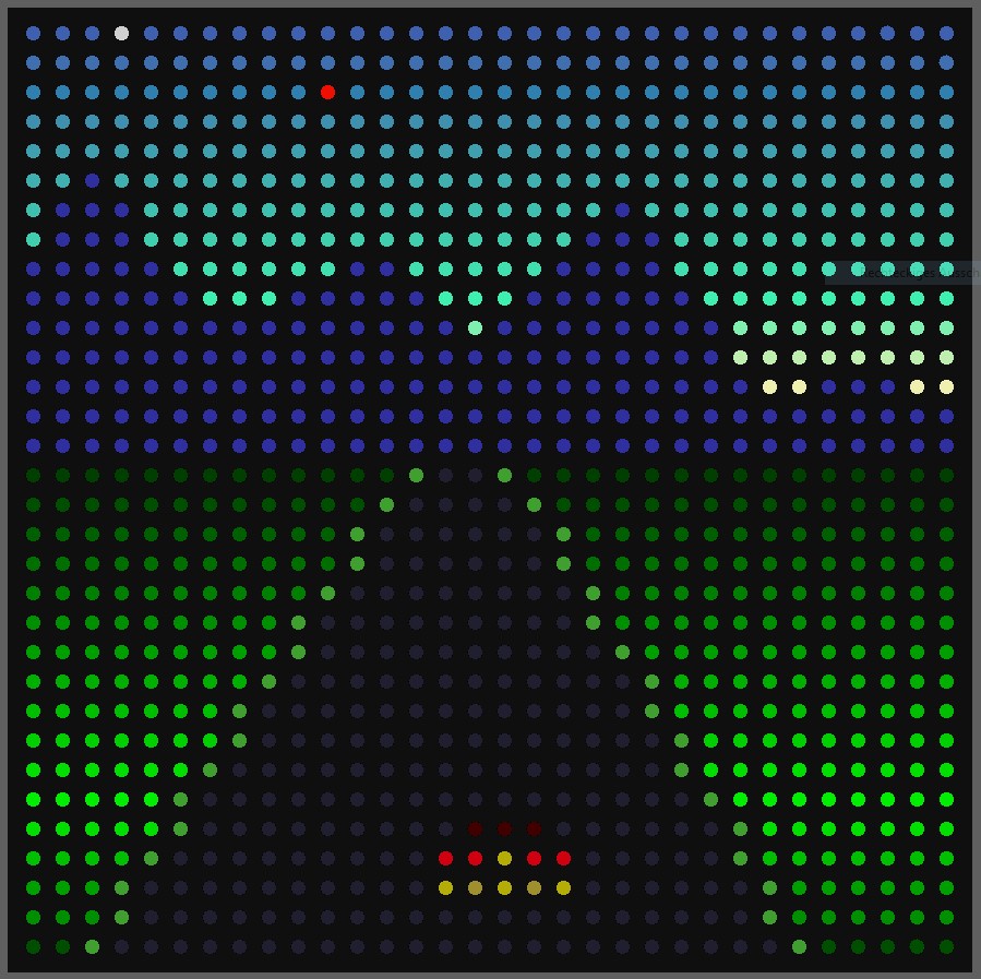
};
The code fragment above has two ingredients, the function showImage() and the array titleImg. showImage() reads the image data from the data structure titleImg. titleImg is made of 32x32 = 1024 numbers between 0 and 16, separated by commas. Each number represents one LED within the LED RGB matrix, the first line of 32 numbers being the first row in the LED matrix. What is the meaning of a number in this context? The number is a color index. In above example, in the image 17 colors between 0..16 were used, with color 0 being the background color = LED off. showImage() reads the numbers one after another and draws a dot = lights an RGB LED with a color that corresponds to the color index. If the color index in the image is 3, the color matrix.Color444(12, 6, 0), is used which is a dark orange.
As titleImg needs to be a global variable, it must be one of the first entries in your code, even before the functions setup() and loop(). Please note that the image data is stored in the Arduino's program memory - the variable modifier PROGMEM is used -, not in variable memory. For further information on how to store immutable data in program memory, please consult the section https://www.arduino.cc/en/Reference/PROGMEM in the Arduino documentation.
The Arduino sketch 'showImage.ino' in the ZIP file demonstrates how you can embed an image in program memory and display it on the LEDmePlay®.
Room for Improvement
There are plenty of possibilities for improving the program. For a better user interface, one could try Peter Lager's G4P GUI controls library from https://www.lagers.org.uk/g4p/index.html
You cannot currently enlarge or shrink the application's window. This is bad practice. If you want this, however, the GUI control elements need to change their size accordingly which might be hard to achieve.
Maybe you would like to edit sprites with LEDmePlay® Draw. For this to be practical, you could mark portions of the image and copy them into a separate buffer which can be saved separately from the rest, or along with several portions. This is something that is likely to be be available in a future version.
The color range in LEDmePlay® Draw differs from that of the real thing. On the LED matrix panel, the colors are considerably brighter. Moreover, due to timing constraints, the electronics of the LED matrix cannot display the full 4096 color spectrum if controlled by an Arduino. An upcoming version of LEDmePlay® Draw will take this fact into account.
License
GNU Lesser General Public License, see https://opensource.org/licenses/LGPL-3.0
Download
Link to the source code: LEDmePlayDraw_1.0.zip