LEDmePlay®
Klicke hier für die deutschsprachige Bastelanleitung!

The construction manual for the LEDmePlay® by Mithotronic® is licensed under a Creative Commons Attribution-NonCommercial-ShareAlike 4.0 International License.
Introduction
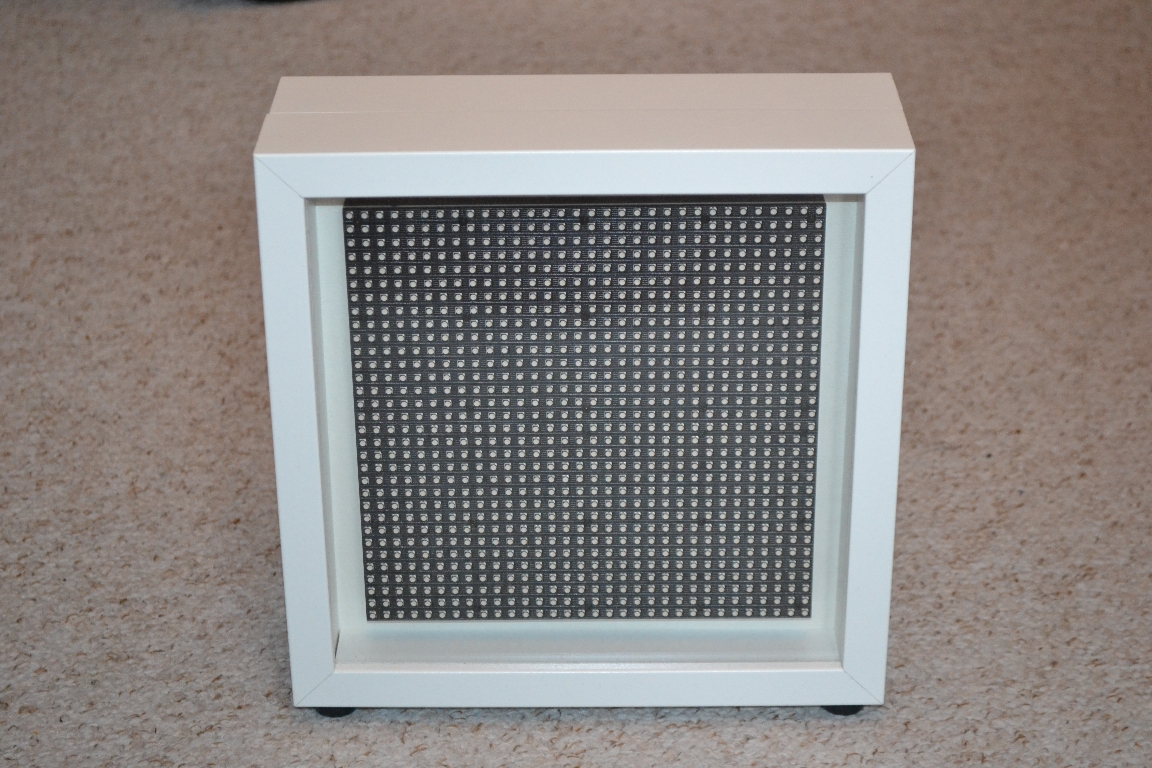
The following sections describe how to build the LEDmePlay® with the appearance shown on this site. Feel free to change parts of our design or add extra features, such as additional buttons, a more fancy housing, a smaller LED matrix. Before you start with the reproduction of the LEDmePlay®, you need to buy the required electronics parts. The main components are the Arduino Mega 2560, the RGB LED matrix, and a suitable power supply. Additionally, you need some cables to connect everything. Whether you plan to use the same picture frames that we used for the housing is up to you. The joysticks need not be the same as ours. Any C64 compatible joysticks from the Eighties era should work. Alternatively, you can build your own LEDmePlay® Joypads, which has the advantages of an analog controller and two fire buttons. Below is the parts list for the LEDmePlay®. Unless otherwise stated, you can buy these or compatible parts from any electronics specialist shop. We paid an overall price of approximately 120 EUR.
Main components
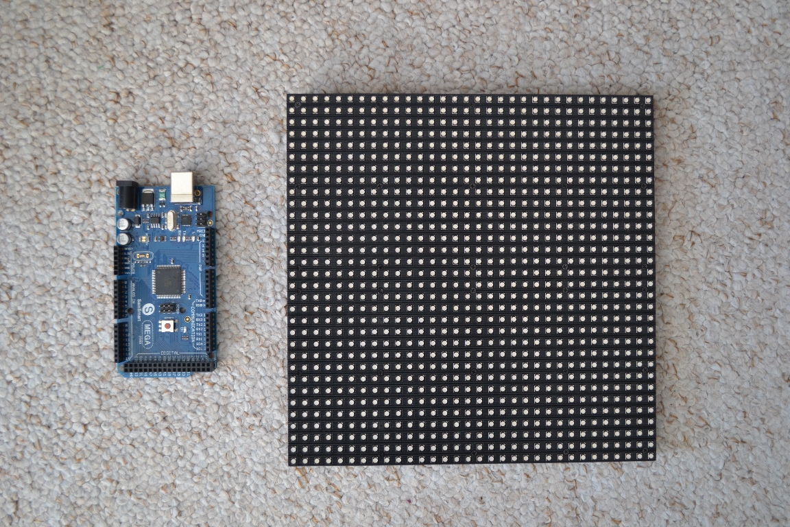
Arduino Mega 2560
RGB LED matrix 32 * 32, e.g., from mechapro GmbH (www.mechapro.de, see product link), from Adafruit (www.adafruit.com, PRODUCT ID: 1484) or a compatible matrix with pixel configuration SMD3528 1R1G1B (P6 which means a pitch of 6mm with the size 192mm * 192mm)
2 * C64/AMIGA-Joysticks (e.g., Competition Pro, Quickjoy, Quickshot) or LEDmePlay® Joypads
switching power supply (5V, 4A) with overload protection (In general 2A should be enough, since the 4A are only required if you set all LEDs to white with highest intensity.)
Note: According to the datasheet, the Arduino Mega 2560 requires a voltage between 7 and 12V at the barrel plug. In the LEDmePlay® only 5V is used. However, we never experienced any issues. Please note, that the RGB LED matrix SHALL NOT be used with more than 5V, since this will cause damage.
Hint: The mechapro GmbH from Germany sells an interface board that simplifies the assembly of the LEDmePlay® and reduces the number of cables you have to solder. Please follow this link for more information.
Connections and buttons
potentiometer 4.7KΩ (linear, for volume control)
knob for potentiometer
2 push buttons (reset, pause)
dip switch (on/off)
2 * 9-pole D-sub male connector (joysticks)
5.5mm female DC connector (connection to power supply)
5.5mm male DC connector (internal connection to Arduino)
small speaker (e.g. LSM-50A-8 with 8Ω)
Cable and other small parts
copper strand (we use a width of 0.22mm2)
ribbon cable (16-pole)
female connector (multi-contact IDC connector) for ribbon cable
multi-pin connector grid dimension 2.54mm (male)
heat shrink tube
4 * distance sleeve
M3 screws (short ones and a few long ones for the Arduino board)
M3 nuts
M3 snap rings
Housing
2 * picture frames model of size 252mm * 252mm * 45mm (from a Swedish home-center)
small woodscrews
Self adhesive protectors as bases
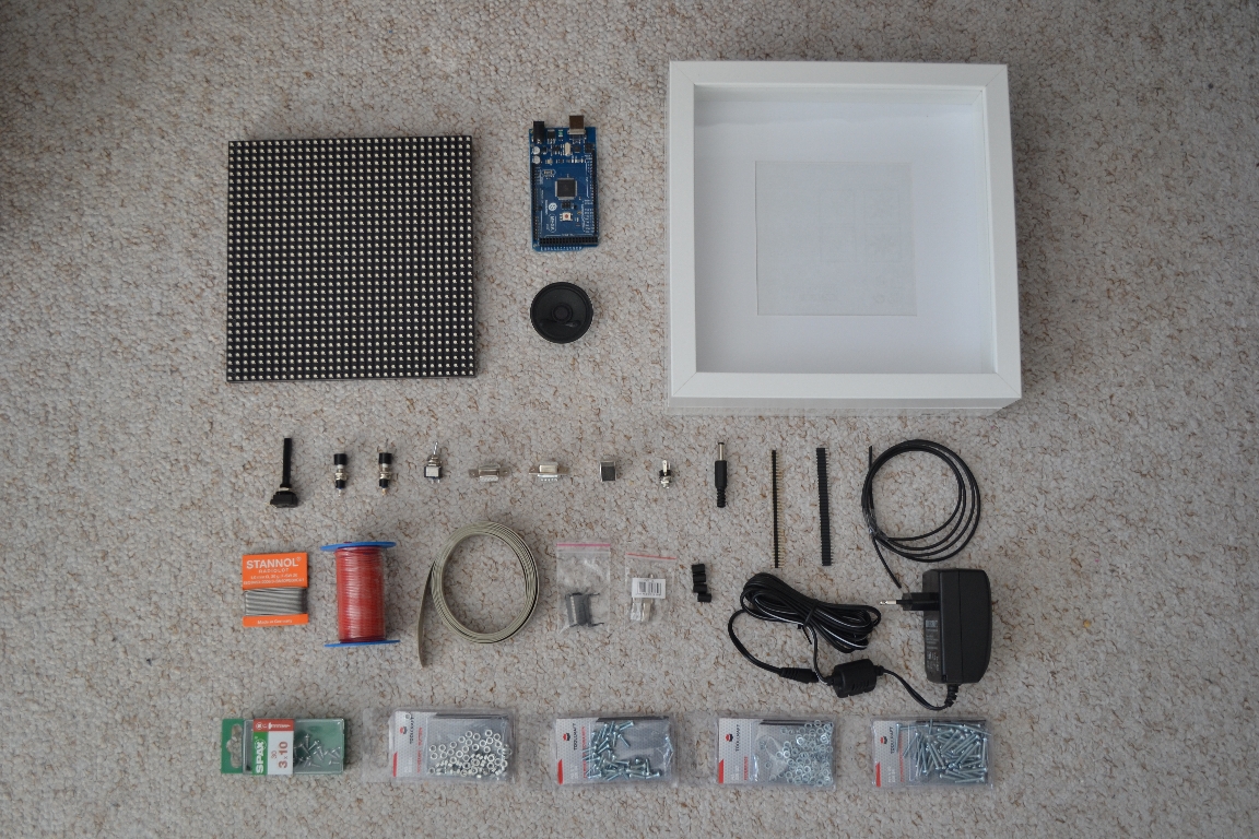
Overview of all parts before starting with the construction:
Preparing the Arduino
Before you start with the construction, we recommend to install the Arduino software on your computer. You will need it to upload our games to the Arduino board and of course if you want to develop your own games. Please check the Arduino homepage where you can find all required information on installation and uploading software (http://www.arduino.cc). Furthermore, you need two libraries for the RGB matrix. These are described on the Adafruit web site. Please check http://learn.adafruit.com/32x16-32x32-rgb-led-matrix/downloads. You can also download them from the following two GitHub projects: AdafruitGFXLibraryMaster and RGBMatrixPanelMaster. The libraries which must be copied to your Arduino directory on your computer. The path could be C:\Program Files (x86)\Arduino\libraries. After that it is useful to upload the LEDmePlay® SelfTest to the Arduino. With this program it is possible to test all functions of the LEDmePlay®, e.g. correct wiring of the color channels, sound, and joystick functions.
Connect the Arduino Mega with the RGB LED matrix and the power supply
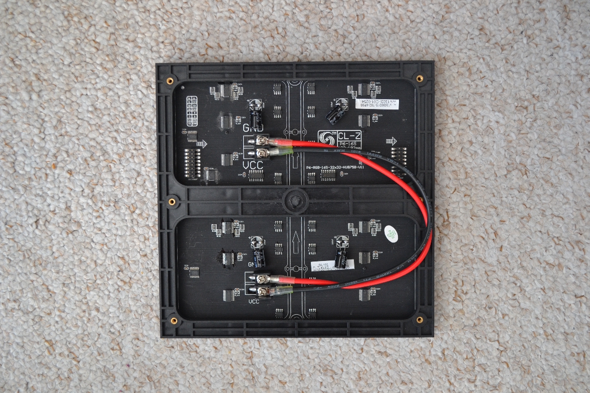
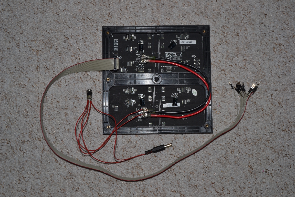
We will now make the connections between the Arduino and the RGB LED matrix. Prior to that you might have to link the two parts of the matrix by power lines which depends on your variant of the matrix. There are different variants in the field like the one shown here on the pictures. If you have this variant, you should have the power lines in the same package as the matrix itself. The upper pins, that correspond to the positive pole, are connected to the red cable as depicted on the right-hand picture. For the alternative variant, this is not required.
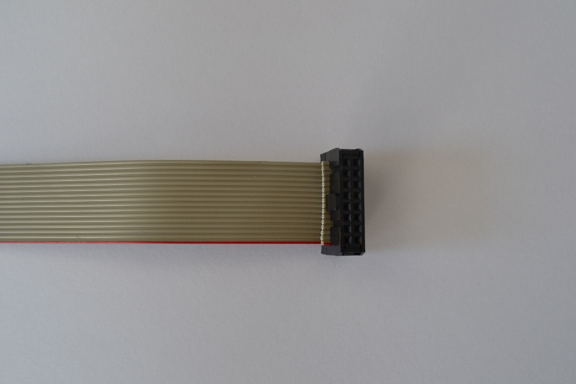
We now need to solder the connection cable. Plug the 16-pole ribbon cable into the female connector on the one side (by compressing the clips of the connector) (cf. picture below on the left-hand side). This end is connected with the matrix. The other end of the cable requires some more work. First, you have to strip the cables. Then you have to solder male pin connectors which are plugged into the Arduino.
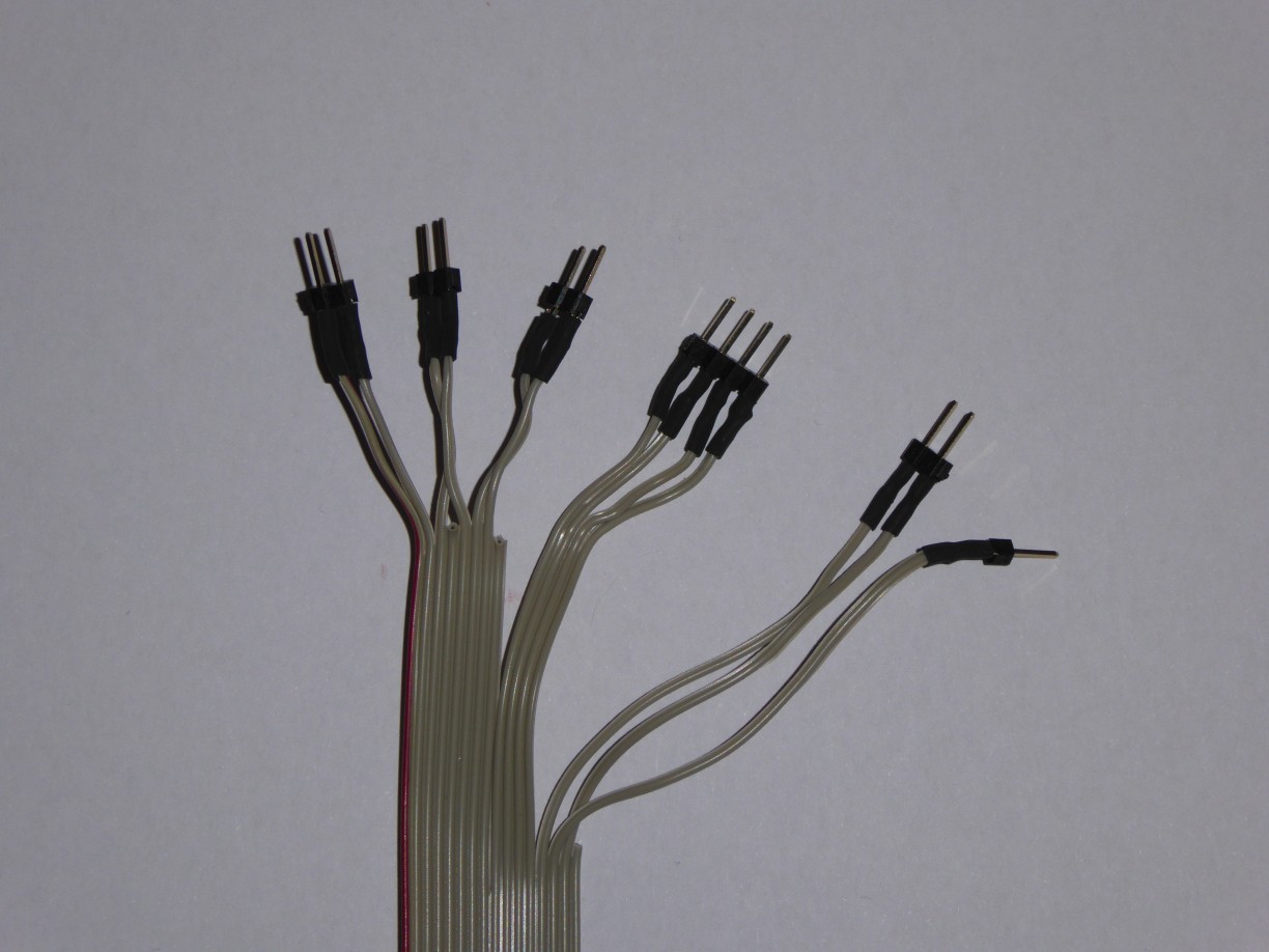
For the connection, the scheme below is required. Cut the multipin connectors into the required sizes (you will need 4 times length 2, length 4, and a single pin). Please use the heat shrink tube before you solder the pins to the cables. After solding, you can heat them e.g., with a hairdryer. See the finished cable end on the picture above on the right-hand side. Note according to the connection scheme below: Some Arduino boards have a misleading pin labeling. Pin 24 and 25 are in the third row of the double-row connector on the right-hand side. The 2*2 pins above remain unused.
Connections between the LED matrix and the Arduino Mega
Pole 1: R1 digital 24 (1st pin of the 1st length 2 multipin connector)
Pole 2: G1 digital 25 (2nd pin of the 1st length 2 multipin connector)
Pole 3: B1 digital 26 (1st pin of the 2nd length 2 multipin connector)
Pole 4: GND not used
Pole 5: R2 digital 27 (2nd pin of the 2nd length 2 multipin connector)
Pole 6: G2 digital 28 (1st pin of the 3rd length 2 multipin connector)
Pole 7: B2 digital 29 (2nd pin of the 3rd length 2 multipin connector)
Pole 8: GND not used
Pole 9: A analog 0 (1st pin of the length 4 multipin connector)
Pole 10: B analog 1 (2nd pin of the length 4 multipin connector)
Pole 11: C analog 2 (3rd pin of the length 4 multipin connector)
Pole 12: D analog 3 (4th pin of the length 4 multipin connector)
Pole 13: CLK digital 50 (1st pin of the 4th length 2 multipin connector)
Pole 14: LAT (STB) digital 10 (single pin)
Pole 15: OE digital 51 (2nd pin of the 4th length 2 multipin connector)
Pole 16: GND not used
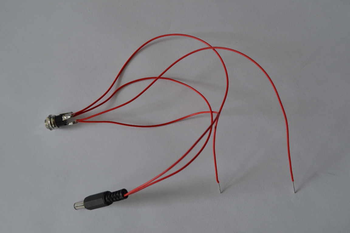
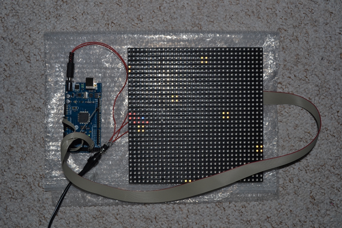
Next is the Y-cable from the power supply to the Arduino and the LED matrix (cf. left-hand picture). You need a female DC connector that fits your power supply. Before you start soldering, consider the polarity. The thick red cable on the matrix shall connect the positive poles. The Arduino is connected via another male DC connector that fits into the power jack. Note that the inner pin of the Arduino jack demands the positive pole. Optionally, you can install an on/off switch between the female DC connector and the power cables that lead to LED matrix and Arduino. Now we are ready for the first test. Make sure that your power adapter is set to 5V and that the polarity is correct. Connect the ribbon cable to the matrix and to the Arduino pins as described above. Then power the matrix and the Arduino with your newly created power cable (cf. right-hand picture).
Ensure that everything has been wired correctly, then switch on the power. After a few seconds the Arduino should start to execute the program and you should see something on the RGB LED matrix (if you have installed the LEDmePlay® SelfTest or a different program before). Congratulations - this was the most challenging part!
Soldering the remaining connectors
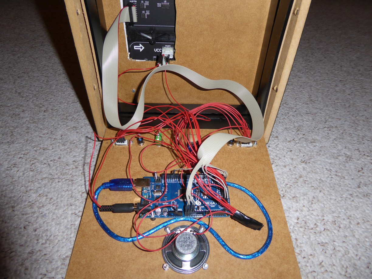
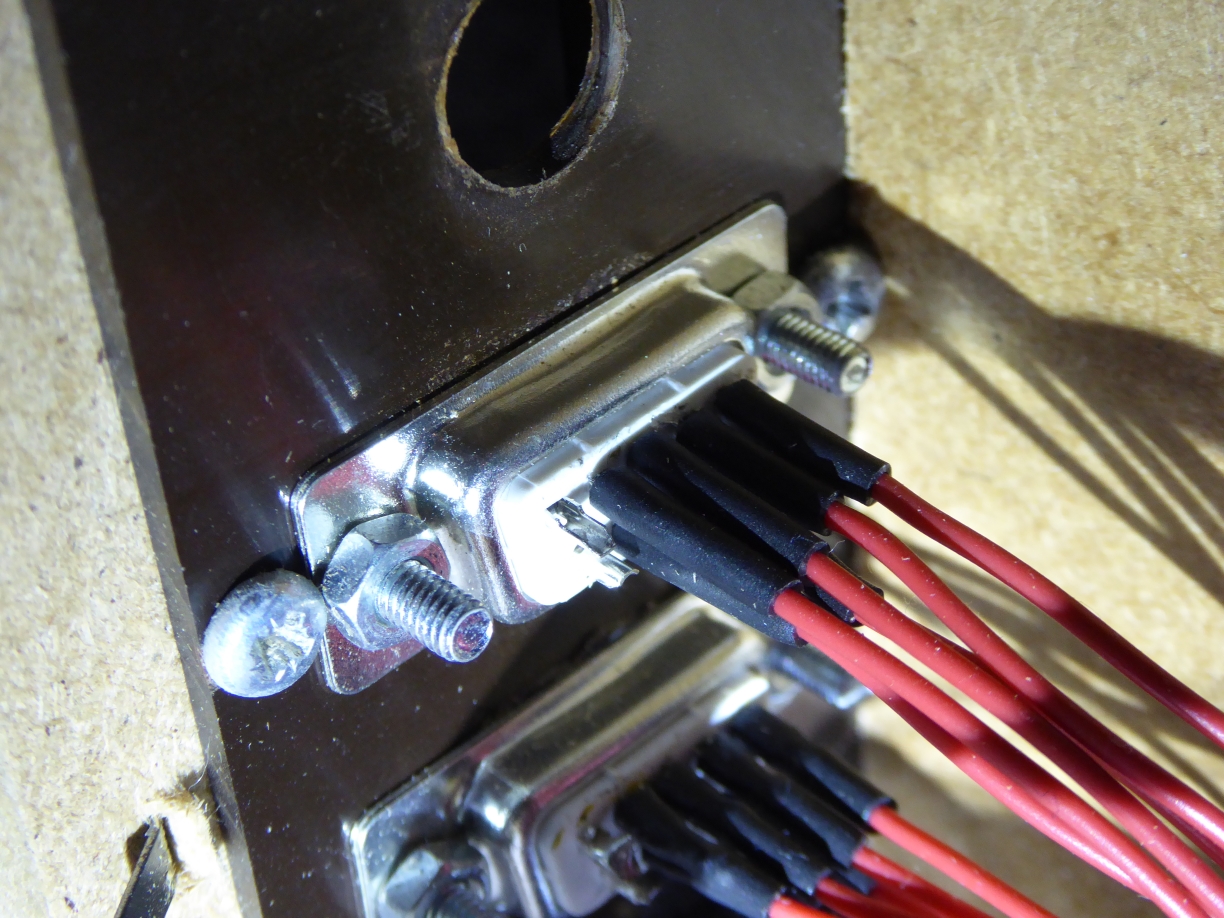
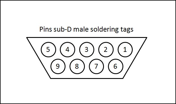
To connect joysticks or LEDmePlay® Joypads, you need 9-pole D-sub male connectors (please see the pin assignment below for the two joysticks). Furthermore, you need to connect the reset and the pause push buttons. The audio pin is soldered directly to the speaker. Looping-in the potentiometer in-between makes the volume adjustable. Please note that you need to link several wires to the Arduino's ground pin (GND): the other pin of the speaker, the second pins of the push buttons and the pin 8 of the D-sub connectors. The following overview shows the pin assignment for the joysticks, the buttons and the speaker.
Other connections
audiopin digital 2 (connected with the potentiometer)
joystick 1 up: D-sub male pin 1 digital 30
joystick 1 down: D-sub male pin 2 digital 32
joystick 1 left: D-sub male pin 3 digital 34
joystick 1 right: D-sub male pin 4 digital 36
joystick 1 analog X (optional if you want to support LEDmePlay® Joypads): D-sub male pin 5 analog 8
joystick 1 fire: D-sub male pin 6 digital 38
joystick 1 5V (optional if you want to support LEDmePlay® Joypads or autofire): D-sub male pin 7 5V
joystick 1 ground: D-sub male pin 8 GND
joystick 1 analog Y (optional if you want to support LEDmePlay® Joypads): D-sub male pin 9 analog 9
joystick 2 up: D-sub male pin 1 digital 31
joystick 2 down: D-sub male pin 2 digital 33
joystick 2 left: D-sub male pin 3 digital 35
joystick 2 right: D-sub male pin 4 digital 37
joystick 2 analog X (optional if you want to support LEDmePlay® Joypads): D-sub male pin 5 analog 10
joystick 2 fire: D-sub male pin 6 digital 39
joystick 2 5V (optional if you want to support LEDmePlay® Joypads or autofire): D-sub male pin 7 5V
joystick 2 ground: D-sub male pin 8 GND
joystick 2 analog Y (optional if you want to support LEDmePlay® Joypads): D-sub male pin 9 analog 11
reset push button digital 42
pause push button digital 43
The pictures below help to assign the pins of the D-sub mal connector. After soldering you are ready to play. Please check our games section.
Housing
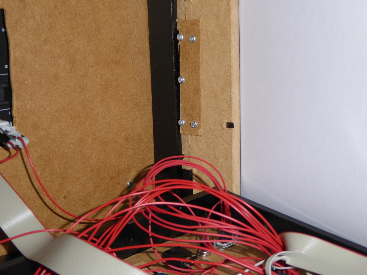
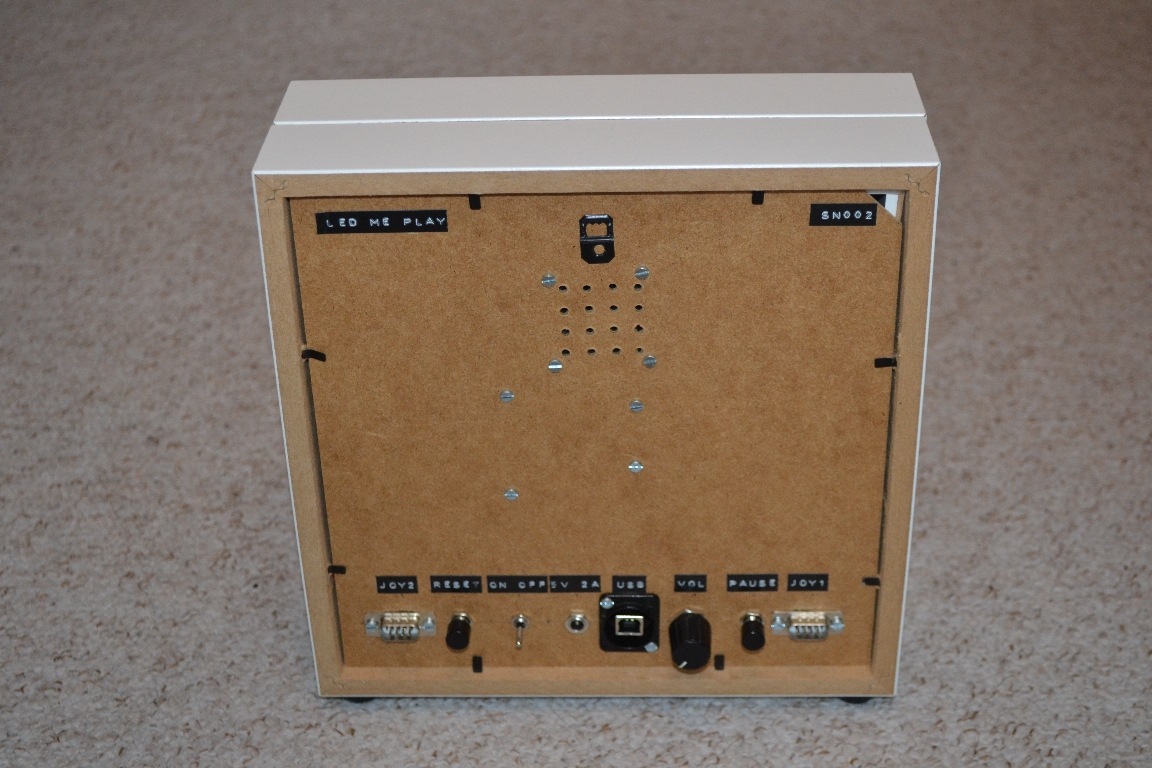
If everything was successful, you can construct a housing. Thereby, the possibilities are endless. We use two picture frames available at a Swedish home-center which are screwed together. The first one contains only the LED matrix which is fixed to the rear panel. That one must be tooled with a saw before, in order to have a rectangular hole for the cables (cf. left-hand picture below). The glass pane of the second frame is removed. The two frames are screwed together at their inner sides using small metal or wooden plates. These are held in place by wood screws (cf. middle of right-hand picture below). The rear panel of the second frame carries the Arduino micro controller board, the speaker, and the connectors. The rear panel can be kept in place by the clamps of the frame when closed. The easiest way to maintain a USB connection to your computer would be to saw a small opening into the rear panel as a cable outlet. Take the short USB cable which is typically delivered with the Arduino and push it through the opening. There you can plug an extension cable. If you have another idea for a housing, please let us know.