LEDmePlay®
Introduction
The LEDmePlayBoy is a handheld variant of the LEDmePlay®. Technically, it is mostly identical and compatible. The same Arduino Mega 2560 is used. Instead of the 6mm pitch (distance between the RGB LEDs) of the original LEDmePlay®, the LEDmePlayBoy uses a compatible matrix with a pitch of 4mm. To control the games, an analog thumb joystick and two fire buttons are used. 8 AA batteries power the device. Of course, also a power supply can be used.
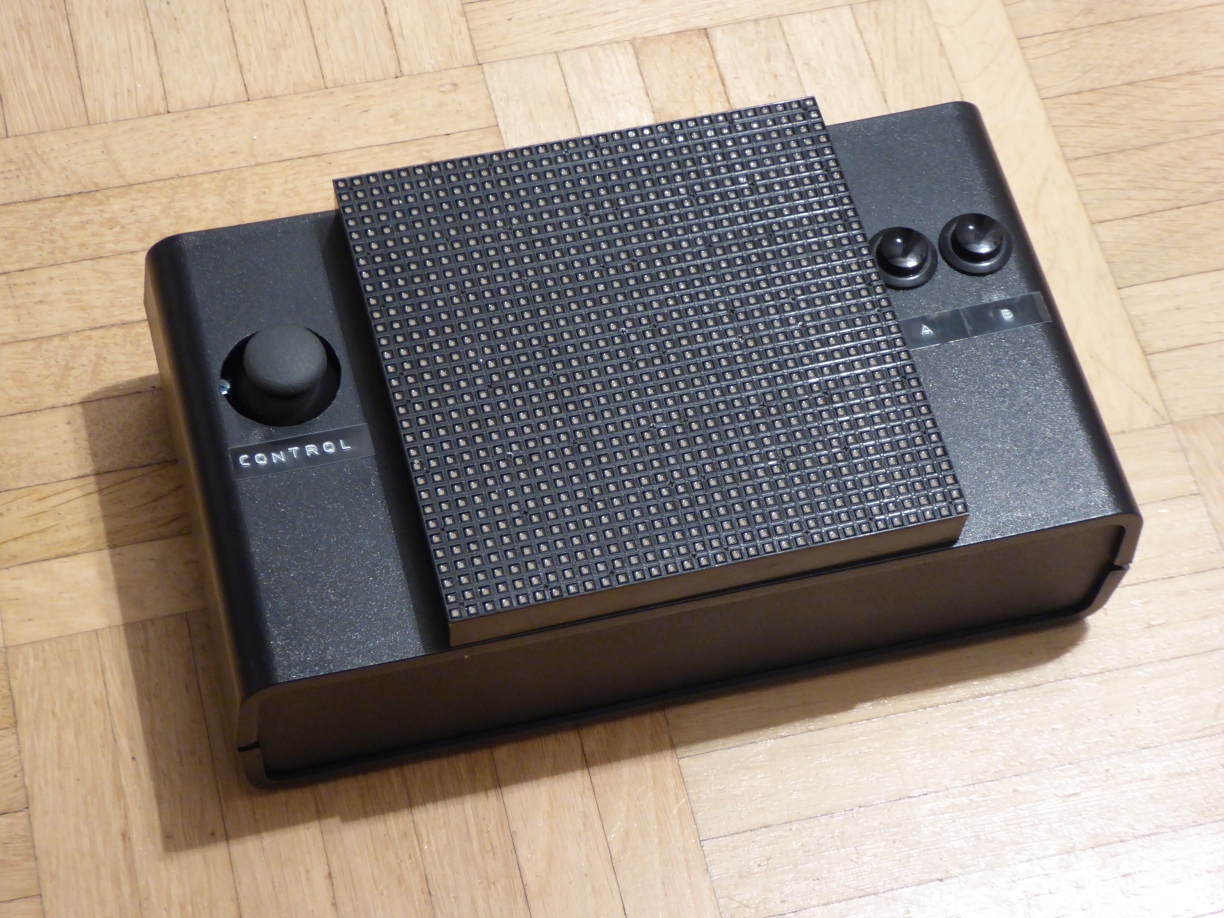
If you want to rebuild the LEDmePlayBoy, the best start is to read the construction manual for the LEDmePlay®. Most of the parts and connections are the same. The list below shows some special parts we suggest for our mobile version. This is no detailed construction manual but more a proposal for a mobile version.
Special components
RGB LED matrix 32 * 32 with a 4mm pitch and pixel configuration SMD3528 1R1G1B
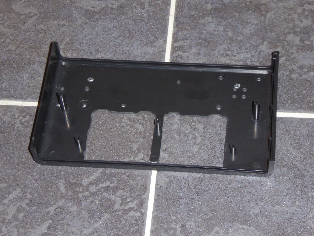
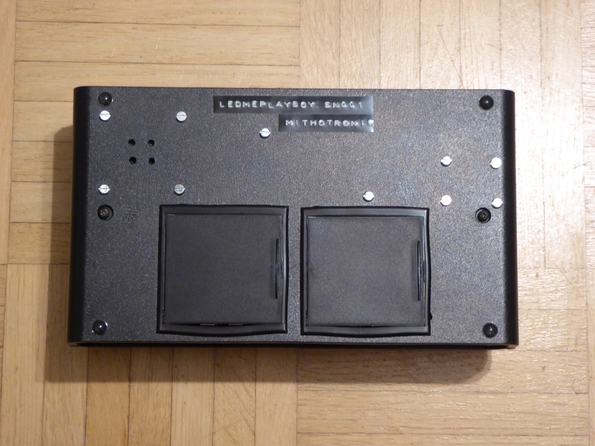
Plastic case (should have a depth of 130mm so that the matrix can be mounted and should have enough space for the Arduino Mega, the joystick, two battery boxes, and a speaker.)
Thumb joystick (Search for "Arduino Joystick". Some of these have an inbuilt fire button which is not required.)
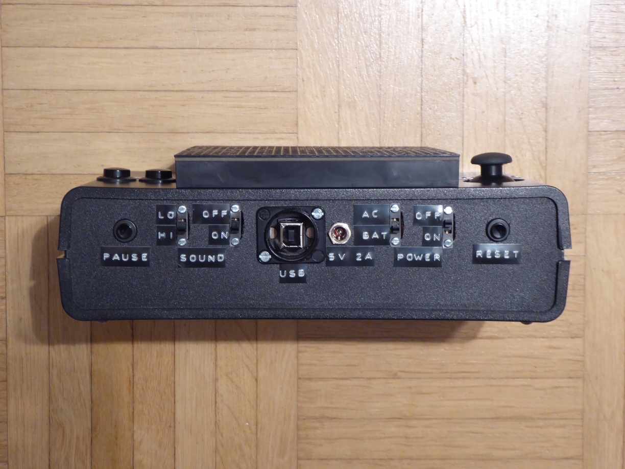
Push buttons (for Fire A, Fire B, Reset, and Pause) which can be mounted in the case cover and the rear panel
2 * battery box (e.g. Bopla 46600000 (65 x 65 x 21.5 mm) by Conrad)
Hints for construction
There are so many plastic cases on the market. It is not easy to suggest a specific one, because it might be problematic for you to procure it. We bought ours at Conrad. The best might be to print your own if you have the possibility. Plastic cases can easily be tooled with a Dremel or a similar device to cut the holes and windows for buttons, connectors, and the matrix.
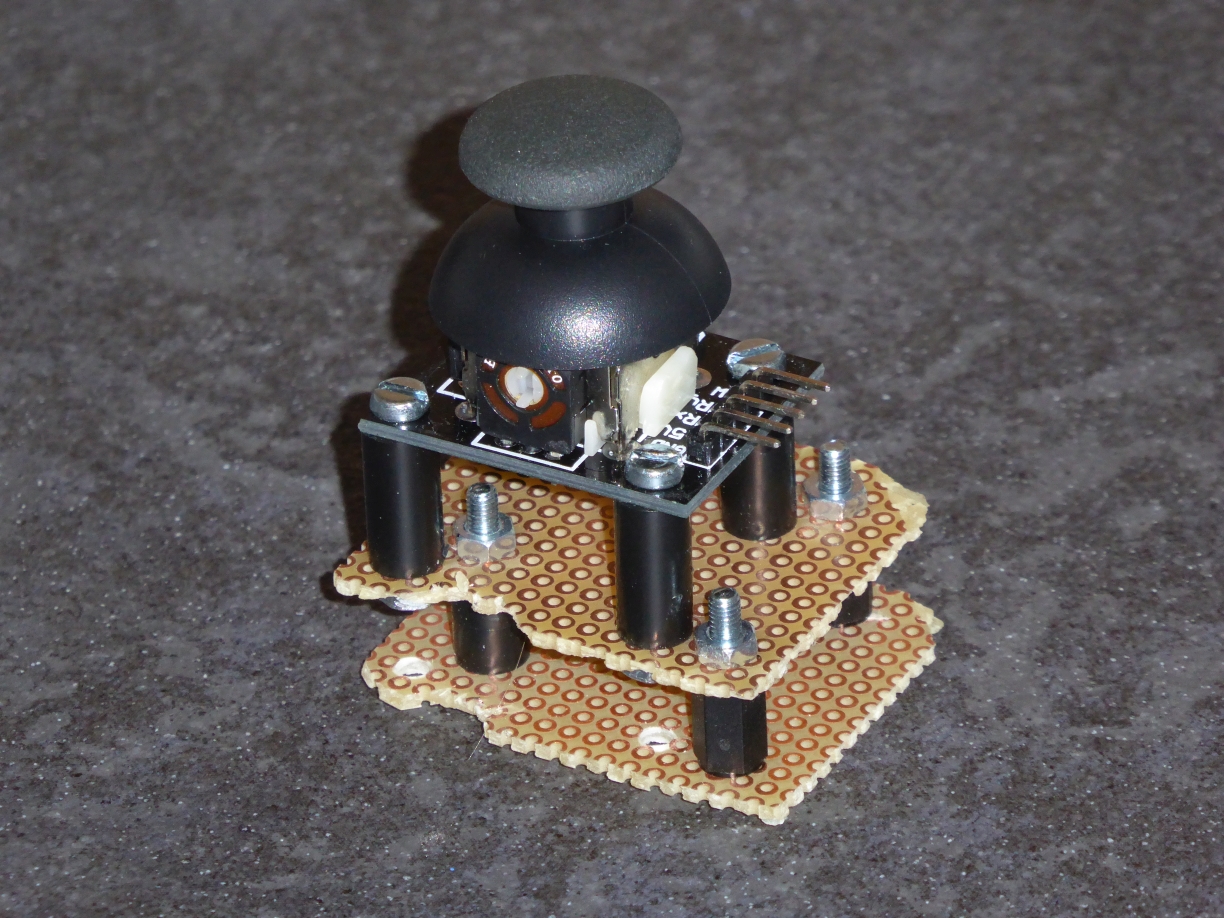
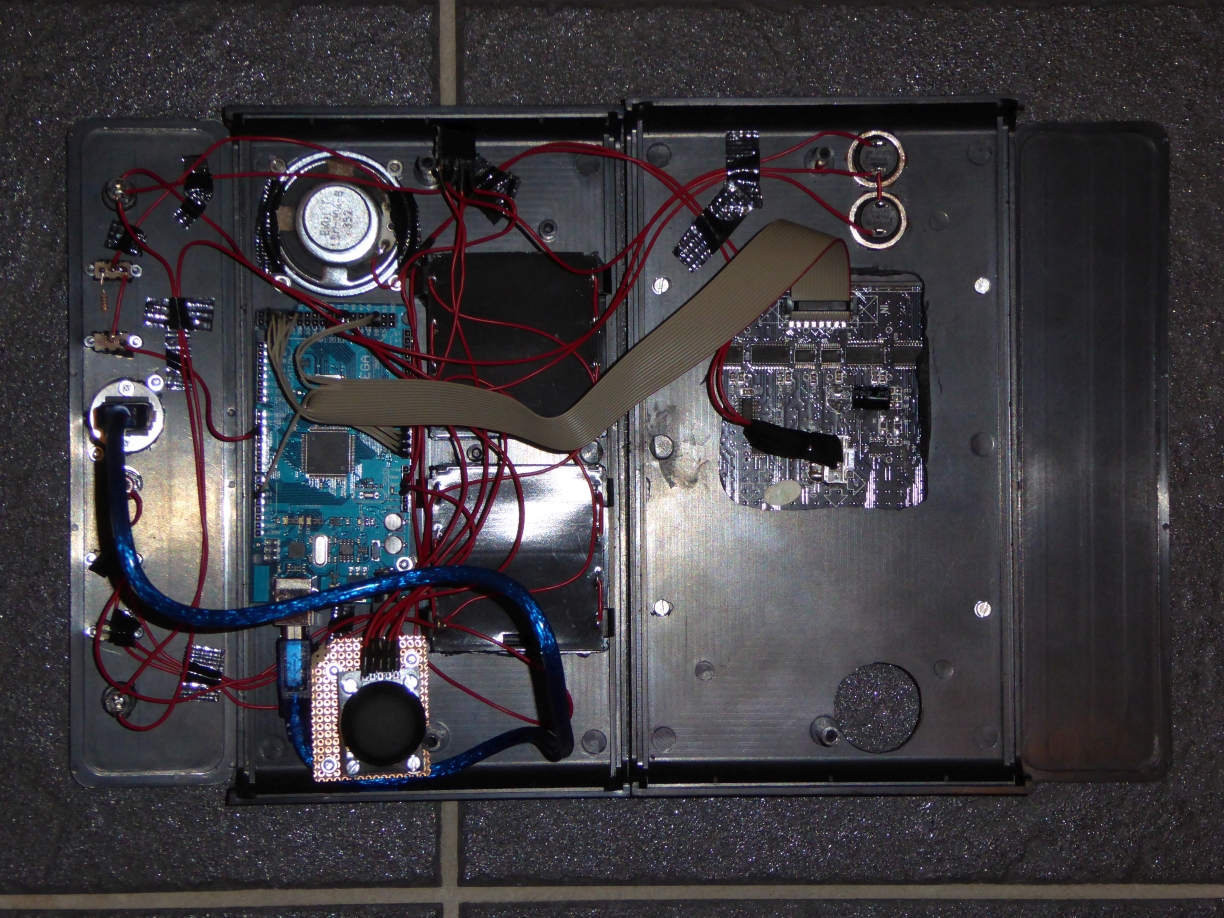
The LEDmePlayBoy uses an analog joystick which must be connected with the analog pins of the Arduino Mega. The wiring scheme is the same as for the LEDmePlay® Joypad (Joy 1). For the X-axis we use analog-in 8. For the Y-axis we use analog-in 9. Fire button A is connected with D38. Fire button B is connected with D30 and D32. Additionally, you have to connected D34 and D36 directly with ground, since this indicates use of a "LEDmePlay® Joypad"-compatible controller in our games. Please note that the thumb joystick must be - in comparison to classic joysticks for the LEDmePlay® - connected with the 5V pin of the Arduino (do not forget the ground pin). For the thumb joystick we created a kind of stand from parts of circuit boards and screws with distance sleeves. It must be optimized for the plastic case so that it brings the joystick into the right height. The stand is then mounted to the rear side of the case so that the joysticks peeks out of a hole cut into the front panel (cf. picture below).
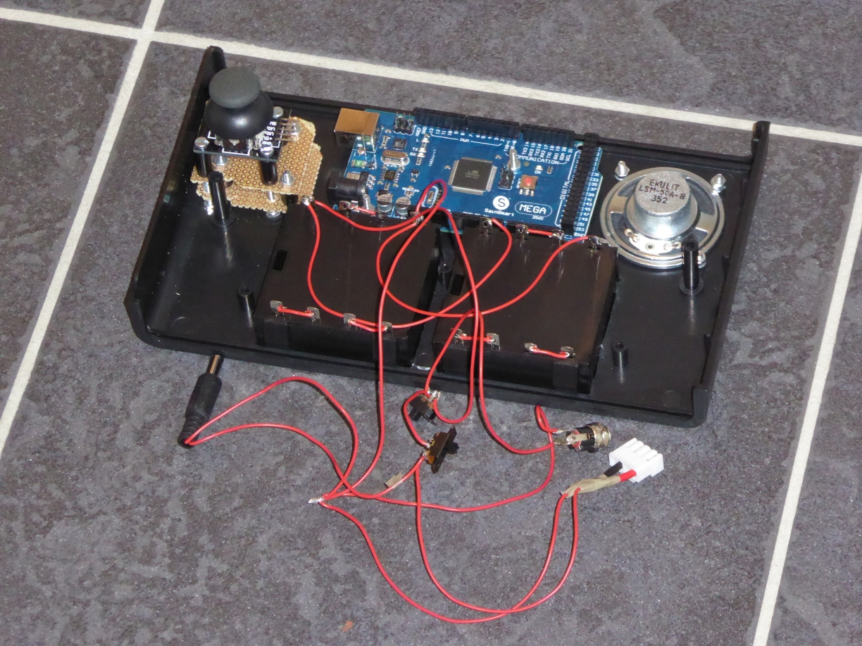
The battery boxes must be connected as a parallel circuit. However, the batteries within a box must be connected in series so that their voltage sums up to 6V. With the two parallel 6V packs, there is enough power to run everything (unfortunately not very long, expect 2 hours depending on the batteries). Since the batteries will be empty soon, you might want to use a power supply. We soldered a switch to toggle between batteries and an AC adapter. We know it is a very inelegant solution but it comes without any electronic parts.
Furthermore, our LED matrix showed strange colors at the first try. We found out that the color assignment differs slightly from the matrix type used for the LEDmePlay®. However, this need not necessarily be the case with every matrix with a 4mm pitch. Just check it. There might be many slightly different variants available. Ours must be connected like that:
Pole 2: R1 digital 25 (2nd pin of the 1st length 2 multipin connector)
Pole 3: G1 digital 26 (1st pin of the 2nd length 2 multipin connector)
Pole 5: B2 digital 27 (2nd pin of the 2nd length 2 multipin connector)
Pole 6: R2 digital 28 (1st pin of the 3rd length 2 multipin connector)
Pole 7: G2 digital 29 (2nd pin of the 3rd length 2 multipin connector)
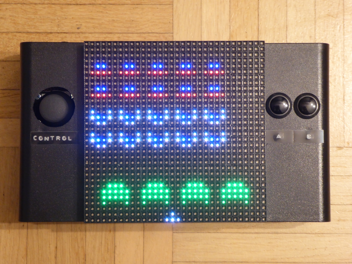
LEDmePlayBoy running "Invaders"on YouTube channel
Comments
7casino, innasurf2002@hotmail.com
On this platform, you can access lots of casino slots from leading developers. Users can experience retro-style games as well as new-generation slots with stunning graphics and interactive gameplay. Whether youre a beginner or an experienced player, theres a game that fits your style. play aviator Each title are ready to play round the clock and compatible with desktop computers and mobile devices alike. You dont need to install anything, so you can jump into the action right away. The interface is intuitive, making it convenient to explore new games. Join the fun, and dive into the thrill of casino games!
Posted: 2025-04-17, 19:48:11
6
gameathlon online casino-Ovals, feuzer1992a@hotmail.com
Stake Online Casino gameathlon.gr is among the best crypto gambling as it was one of the pioneers. The online casino market is growing rapidly and players have a vast choice, but not all casinos offer the same experience. In this article, we will review the most reputable casinos accessible in the Greek region and the benefits they offer who live in Greece specifically. Best online casinos of 2023 are shown in the table below. Here are the top-ranking gambling platforms as rated by our expert team. For every casino, it is essential to verify the validity of its license, software certificates, and security protocols to guarantee safe transactions for players on their websites. If any of these factors are absent, or if we have difficulty finding them, we exclude that website from our list. Software providers also play a major role in determining an internet casino. As a rule, if theres no valid license, you wont find trustworthy software developers like Microgaming represented on the site. Top-rated online casinos offer classic payment methods like Mastercard, and they should also offer digital payment services like Paysafecard and many others.
Posted: 2025-03-22, 06:58:18
5
gameathlon online casino-Ovals, feuzer1992a@hotmail.com
Stake Casino GameAthlon Casino is among the best cryptocurrency casinos since it integrated crypto into its transactions early on. The online casino market has expanded significantly and the choices for players are abundant, however, not all of them are created equal. This article, we will take a look at the best casinos accessible in the Greek region and the benefits they offer who live in Greece specifically. Best online casinos of 2023 are shown in the table below. Here are the best casino websites as rated by our expert team. For any online casino, make sure to check the licensing, security certificates, and data security policies to guarantee safe transactions for users on their websites. If any of these elements are missing, or if its hard to verify them, we avoid that platform. Casino software developers are crucial in selecting an internet casino. As a rule, if the above-mentioned licensing is missing, you wont find reliable providers like Microgaming represented on the site. Reputable casinos offer known payment methods like Visa, but should also provide e-wallets like Skrill and many others.
Posted: 2025-03-21, 14:43:45
4
gameathlon.gr-Ovals, feuzer1992a@hotmail.com
Stake Casino gameathlon.gr is considered one of the top online gambling platforms since it was one of the first. The digital casino industry is growing rapidly and there are many options, however, not all of them provide the same quality of service. This article, we will review top-rated casinos you can find in the Greek market and the benefits they offer who live in the Greek region. The top-rated casinos of 2023 are shown in the table below. Here are the highest-rated casinos as rated by our expert team. When choosing a casino, it is essential to verify the licensing, gaming software licenses, and data protection measures to ensure safety for players on their websites. If any important details are missing, or if we have difficulty finding them, we avoid that platform. Gaming providers also play a major role in determining an online casino. Generally, if the above-mentioned licensing is missing, you wont find trustworthy software developers like Microgaming represented on the site. The best online casinos offer classic payment methods like Mastercard, and they should also offer e-wallets like Neteller and many others.
Posted: 2025-03-20, 06:55:18
3
gameathlon.gr-Ovals, feuzer1992a@hotmail.com
Stake Casino gameathlon.gr is one of the leading cryptocurrency casinos since it integrated crypto into its transactions early on. Online gambling platforms is growing rapidly and there are many options, not all online casinos provide the same quality of service. In this article, we will take a look at the most reputable casinos you can find in Greece and the benefits they offer who live in Greece specifically. The best-rated casinos this year are shown in the table below. The following are the highest-rated casinos as rated by our expert team. When choosing a casino, make sure to check the legal certification, security certificates, and security protocols to guarantee safe transactions for users on their websites. If any important details are missing, or if its hard to verify them, we do not return to that site. Casino software developers are another important factor in choosing an online casino. As a rule, if the above-mentioned licensing is missing, you wont find reliable providers like Microgaming represented on the site. Reputable casinos offer known payment methods like Mastercard, and they should also offer electronic payment methods like Skrill and many others.
Posted: 2025-03-19, 10:54:02
Previous comments | Next comments