Infinity Mirror
Introduction
This manual describes how to construct the infinity mirror in the same design as presented on this site. Of course, there are endless ways to change the design, the size or even the controlling device and the software. If you follow our manual, the overall price of all components will be around 100 EUR. Before you start with the construction, we recommend to install the Arduino software on your computer. You will need it to upload the software for the infinity mirror to the Arduino board. Please check the Arduino homepage where you can find all required information on installation and uploading software: http://www.arduino.org. Additionally, you need the NeoPixel library for the RGB LED strip which is available via the Adafruit web site. Please check https://learn.adafruit.com/adafruit-neopixel-uberguide which contains detailed information (which is very useful in a variety of ways). Follow the links to the Arduino library. The files Adafruit_NeoPixel.h and Adafruit_NeoPixel.cpp must be stored in a folder by the name Adafruit_NeoPixel. You need to copy this folder to your Arduino library directory on your computer. The path could be C:\Program Files (x86)\Arduino\libraries.
Components for the mirror
2 * RGB LED Strips (Black 60 LED - 1m) from Adafruit (www.adafruit.com, PRODUCT ID: 1461) or a compatible ones (sometimes 2m long strips are available)
Picture frame of size 524mm * 524mm * 45mm (from a Swedish home-center)
Mirror 500mm * 500mm which can replace the rear panel of the picture frame (we got our custom made mirror from www.mein-wandspiegel.de)
3.5mm stereo jack plug
double-faced adhesive tape
Components for the controller
Arduino UNO
Small plastic box, to be used as a housing
2 push buttons (reset, pause)
Mountable LED (optional)
3.5mm stereo jack plug
multi-pin connector (male)
copper strand (for internal connections)
heat shrink tube
4 * distance sleeve
M3 screws (to mount the Arduino board)
M3 nuts
M3 snap rings
Power device and cable
Power supply 5V, 10A (Yes, it really required 10A!)
Cable with 3.5mm stereo phone jacks (connects the controller with the infinity mirror)
Construction of the infinity mirror
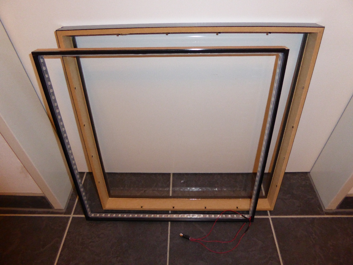
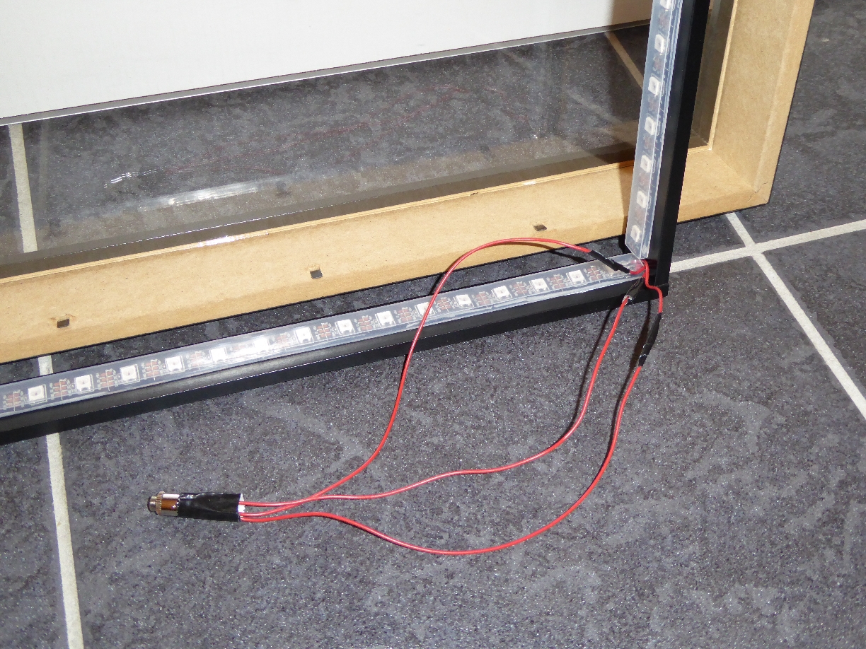
The construction of the mirror is very easy if you have a fitting frame. You simply need to open the frame and glue the RGB LED strips to the inner face. For this matter, we have used a removable inner frame. Prior to glueing, you should convince yourself that the LED strips have the required length. The two LED strips can be connected by three short wire straps by soldering. Furthermore, the strips can also be cut at an arbitrary position between two LEDs. We needed 116 of the 120 LEDs and were lucky to have a 200cm long strip, so that there was no need to connect the LED strips. You should solder short cables to the three contacts at one end of the strip, processed to the correct length, which will serve as connection to the controller. To this end, a 3.5mm stereo jack plug is soldered to the other end of the cables. After that you can glue the strip. The easiest way is to use double-faced adhesive tape. The best thing would be to start in one of the corners (cf. pictures below).
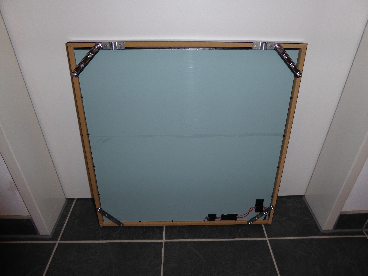
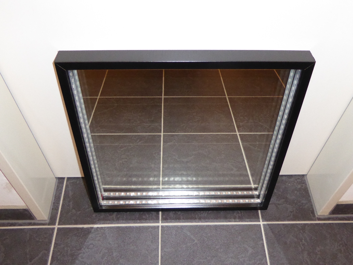
After that, you can assemble the frame. Note that the rear panel is replaced by the mirror. Since the mirror weighs more than the pressboard panel, it is useful to add some metal plates by using wood screws. This increases the stability (cf. pictures below). The cable can be attached to the rear side of the mirror by means of duct tape.
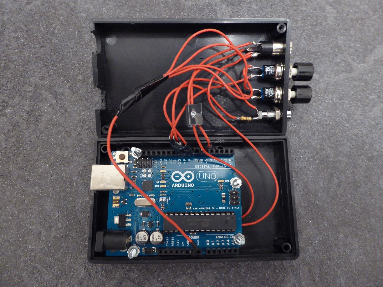
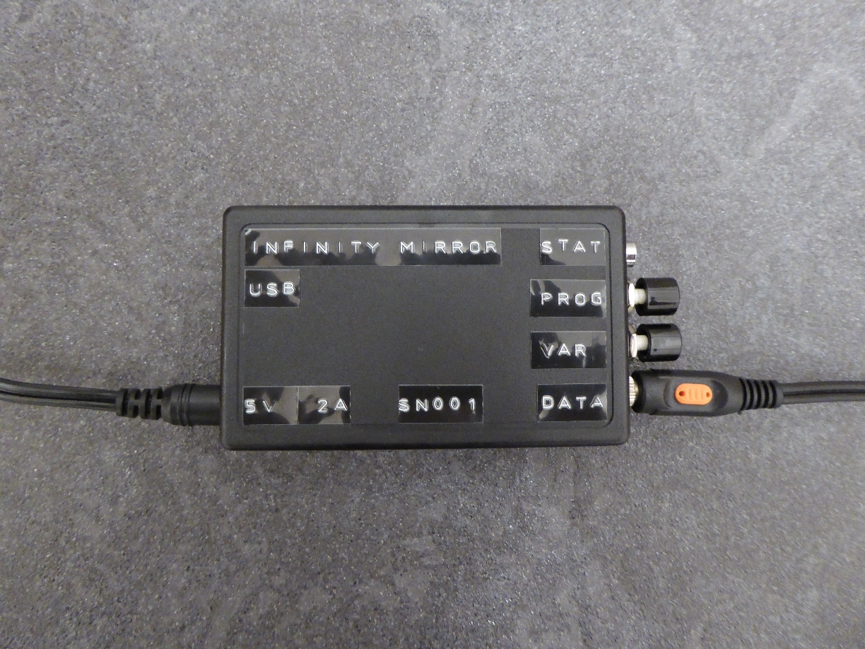
Construction of the controller
In the plastic box, drill some holes for the connections and the screws. Of course, the particular positions depend on the specific dimensions of the device. We mounted the Arduino board nearby the left side, so that the power and USB plugs can directly be inserted into the board. Additionally, you need space for the two push buttons, the mountable LED, and the stereo jack plug. However, the LED is optional. It will indicate that the system has detected the push of a button. In order to be compatible to the NeoPixel library and to our software, the following connections have to be made. To make the connections, you can solder cables to single cropped pins of the multi-pin connector. Heat shrink tube will protect the solder joints.
LED strip data line digital 6
Control LED digital 8
Button to change program digital 9
Button to change variation digital 10
The returning cables from the control LED, the buttons, and the ground wire from the LED strip (from the stereo jack plug) are wired together and connected to the ground pin of the Arduino board. Moreover, two cables are soldered to the power supply contacts on the rear side of the Arduino board. The 5V contact is soldered to the stereo jack plug pin which is connected to the 5V pin of the Arduino strip. The ground contact is soldered to the stereo jack plug ground pin which has already been connected to the ground pin of the Arduino board. After that, the wiring is finished.
Controller software
Link to the source code: infinity_mirror_1_0.ino